اختيار الصمامات المخصصة للاستخدامات القاسية: المعايير الهندسية والمعايير الفنية وأنماط الأعطال
Severe service valve selection is a system-engineering task rather than a catalogue exercise. Nominal size and pressure class identify only part of the requirement. A technically defensible selection must also address the process envelope, valve function, pressure-temperature rating, flow behavior, material degradation mechanisms, seat leakage, atmospheric emissions, actuator capability and inspection acceptance criteria.
A valve may comply dimensionally with a recognized standard and still fail in service. Typical causes include cavitation at the trim, flashing erosion downstream of the seat, chloride attack on an unsuitable stainless steel, sulfide stress cracking in sour service, excessive operating torque, thermal contraction in cryogenic duty and unstable control caused by oversizing.
1. Severe Service Valve Selection Starts with the Design Basis
The design basis must describe the complete operating envelope, not only the normal operating point. Transient conditions during start-up, shutdown, regeneration, line packing, pump trip or emergency isolation may impose a greater load than steady operation.
| Required data | Engineering significance | Frequent specification error |
|---|---|---|
| Fluid composition and phase | Controls corrosion, elastomer compatibility, toxicity and flow model | Writing only “water,” “gas” or “chemical” |
| Design and operating pressure | Defines pressure boundary and normal valve loading | Using pump discharge pressure without surge review |
| Design and operating temperature | Affects pressure rating, toughness, packing, seats and bolting | Checking body material but not soft-seat limits |
| Maximum differential pressure | Controls torque, thrust, trim velocity and cavitation risk | Sizing the actuator at normal differential pressure |
| Flow rate, density and viscosity | Required for Cv/Kv sizing and velocity assessment | Selecting the line-size valve without a flow calculation |
| Vapor and critical pressure | Required for choked-flow, flashing and cavitation analysis | Ignoring vapor pressure for hot liquid service |
| Solids and particle distribution | Influences erosion, blockage, seat protection and flushing | Specifying only solids percentage without particle size |
| Cycles and required stroke time | Affects packing endurance, actuator duty and surge | Requesting “fast closing” without transient analysis |
2. Build a Standards Hierarchy Instead of Listing Random Standards
No single standard completely specifies an industrial valve. A complete procurement document normally combines a piping code, pressure-boundary standard, valve product standard, connection standard, test standard and service-specific qualification.
| Requirement | Typical reference | What it establishes |
|---|---|---|
| Pressure-temperature rating | ASME B16.34 | Materials, ratings, examination, testing and marking framework |
| Pipeline valves | API 6D | Requirements for pipeline and piping valve designs |
| Valve pressure testing | API 598 or ISO 5208 | Shell integrity, closure testing and acceptance |
| Control-valve sizing | IEC 60534-2-1 | Installed flow-capacity equations and correction factors |
| Fugitive emissions | ISO 15848-1, API 624 or API 641 | Type qualification of stem or shaft sealing systems |
| Sour oil and gas service | NACE MR0175/ISO 15156 | Selection of cracking-resistant metallic materials |
| Fire qualification | API 607 or API 6FA | Leakage performance during and after a defined fire test |
The purchase order should identify the required edition. A statement such as “manufactured according to API” is not technically complete because API 6D, API 598, API 607 and API 641 address different aspects of valve performance.
3. Pressure Class Is Not the Maximum Allowable Pressure
ASME pressure class is a designation, not a constant pressure limit. Allowable pressure changes with material group and temperature. The valve body, bonnet, end connections, bolting, packing, gasket and seat must all remain suitable at the design condition.
The following checks are separate and all are required:
- Body and bonnet pressure-temperature rating
- Flange or welding-end compatibility with the piping class
- Low-temperature impact toughness where applicable
- High-temperature strength and oxidation resistance
- Bolting and gasket temperature capability
- Soft-seat, elastomer and packing temperature limits
- Thermal expansion between body, trim and seat components
A Class 600 body does not make a polymer seat suitable for the same temperature envelope. The lowest-rated pressure-retaining or sealing component limits the assembly.
4. Select the Valve Architecture by Function and Failure Mode
| Duty | Common architecture | Critical review |
|---|---|---|
| عزل خط الأنابيب بالكامل | Trunnion-mounted ball valve | Seat arrangement, cavity relief, stem retention and operating torque |
| General process isolation | Gate or ball valve | Seat leakage, deposits, thermal locking and maintenance access |
| Accurate throttling | Globe-style control valve | Cv, rangeability, noise, cavitation, actuator stiffness and shutoff load |
| Large-diameter isolation | Double- or triple-offset butterfly valve | Disc interference, dynamic torque, seat retention and installation clearance |
| Reverse-flow prevention | Swing, axial, piston or dual-plate check valve | Minimum velocity, closing response, slam and installation orientation |
| Abrasive slurry isolation | Knife gate or slurry valve | Gate guidance, solids packing, flushing, wear parts and bidirectionality |
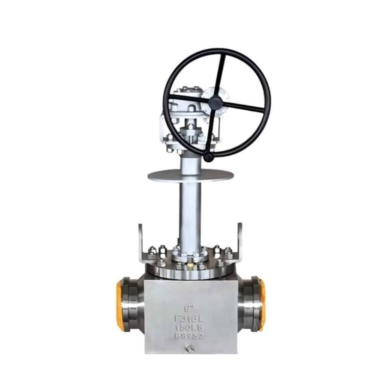
| Cryogenic isolation | Extended-bonnet ball, gate or globe valve | Packing temperature, orientation, trapped-cavity relief and thermal contraction |
Conventional gate valves should not be used for continuous throttling. Partial opening concentrates velocity around the gate and seat, increasing vibration, wiredrawing and erosion. Quarter-turn valves can provide control, but their pressure-recovery characteristics and dynamic torque must be evaluated rather than inferred from nominal Cv alone.
5. Cv and Kv Are Capacity Coefficients, Not Selection Certificates
For a preliminary non-vaporizing liquid calculation in US customary units:
Cv = Q × √(SG / ΔP)
where Q is flow in US gallons per minute, SG is specific gravity and ΔP is valve pressure drop in psi. The approximate relationship between the two common coefficients is:
Kv ≈ 0.865 Cv
This simplified relationship is not adequate for final severe service valve selection. IEC 60534-2-1 calculations introduce corrections for installed reducers, viscosity, pressure recovery, liquid critical pressure, vapor pressure and choked flow. Compressible gases require a different flow model. Slurries and non-Newtonian fluids may fall outside the normal equations and require application-specific testing or validated correlations.
Oversizing is a frequent control-valve error. An oversized valve may operate close to its seat during normal production, reducing useful travel and control resolution. The trim can then experience high localized velocity even though the body size appears conservative.
6. Cavitation and Flashing Require Different Solutions
Cavitation
Cavitation begins when pressure at the vena contracta falls below liquid vapor pressure and then recovers above vapor pressure downstream. Vapor bubbles form and collapse, producing localized impact, noise, vibration and a rough, porous erosion pattern.
A simplified condition is:
Pvc < Pv and P2 > Pv
Effective mitigation may include multi-stage pressure reduction, anti-cavitation cages, increased downstream backpressure, valve relocation, controlled flow direction and hardened trim. Multi-stage trim is intended to divide one large pressure drop into several smaller drops so local pressure does not fall below the vapor pressure.
Flashing
Flashing occurs when downstream pressure remains below vapor pressure:
P2 < Pv
The vapor phase remains downstream and does not collapse. Flashing therefore cannot normally be eliminated inside the valve. The design objective becomes management of high-velocity two-phase flow through body geometry, outlet sizing, flow direction and erosion-resistant materials. Cavitation-resistant trim alone does not solve a flashing application.
For severe pressure-reduction duties, see WDL Valve’s industrial control valve solutions.
7. Material Selection Must Follow the Damage Mechanism
Material selection should be based on the expected degradation mechanism rather than a simple hierarchy in which every higher alloy is assumed to be better.
Carbon and low-alloy steels
Carbon steel is appropriate for many non-corrosive oil, gas, steam and water services. Low-temperature grades may be required for impact toughness. Chromium-molybdenum alloys may be selected where elevated-temperature strength and oxidation resistance are required.
Austenitic stainless steels
316 and CF8M improve general corrosion resistance but remain susceptible to chloride pitting, crevice corrosion and chloride stress-corrosion cracking. Chloride concentration, temperature, oxygen, deposits and crevice geometry must be reviewed.
Duplex and super duplex stainless steels
Duplex grades combine higher mechanical strength with improved resistance to chloride stress-corrosion cracking. Performance still depends on exact grade, heat treatment, ferrite balance, welding procedure and environmental limits. Review WDL Valve’s duplex stainless steel valve capabilities for seawater and chloride-rich service.
Nickel alloys, titanium and zirconium
Nickel alloys may be selected for strong acids, reducing conditions, high temperature or mixed corrosion environments. Titanium is effective in many oxidizing chloride services, while zirconium is used in selected severe acid applications. The exact alloy designation must be specified; terms such as “nickel alloy trim” or “special alloy body” are not adequate procurement descriptions.
Sour service
NACE MR0175/ISO 15156 material selection depends on hardness, metallurgical condition, H2S partial pressure, pH, chloride concentration, temperature and applied stress. A material name alone does not establish sour-service compliance. Manufacturing records must also preserve the qualified heat treatment and hardness condition.
8. Seat Leakage and Fugitive Emissions Are Different Requirements
Seat leakage concerns internal flow past the closed obturator. Fugitive emissions concern atmospheric leakage through the stem or shaft seal and body joints.
A seat-leakage specification should state:
- Test standard and edition
- Test medium and pressure
- Test direction
- Duration
- Permitted leakage rate
- Whether acceptance occurs before or after functional cycling
“Zero leakage” has no useful procurement meaning unless the test method and acceptance threshold are defined.
For atmospheric emissions, ISO 15848-1 provides a classification and type-qualification framework. API 624 applies to rising-stem valves equipped with graphite packing, while API 641 applies to quarter-turn valves. A qualification certificate should be checked for valve type, size range, pressure class, packing system, temperature class and mechanical-cycle scope.
9. Fire-Safe Does Not Mean Fireproof
A fire-tested valve is designed to limit leakage during and after a defined fire exposure. The qualification does not imply that the valve remains undamaged or can be returned to service without inspection.
API 607 is commonly applied to quarter-turn valves and valves fitted with nonmetallic seats. API 6FA addresses fire testing of valves more broadly. The project must specify the applicable standard and confirm that the tested configuration represents the supplied valve.
Secondary metal seating, antistatic continuity and stem retention may all be important, but they are separate design requirements and should be stated explicitly.
10. Actuator Selection Must Use the Worst Credible Load
The actuator must be sized from required torque or thrust at the worst credible condition, not from nominal valve size.
- Break-to-open and end-to-close load
- Maximum differential pressure
- Seat and packing friction
- Hydrodynamic or aerodynamic torque
- Minimum pneumatic or hydraulic supply pressure
- Motor starting torque for electric actuation
- Temperature, deposits and aging effects
- Required operating time and fail action
- Stem, gearbox, bracket and coupling allowable loads
Excess actuator output is not automatically safer. It can overload the stem, key, coupling, seat or mechanical stops. The valve and actuator must be assessed as one drive train.
Fast emergency closure also requires a hydraulic-transient review. Reducing stroke time without checking surge pressure can transfer risk from the valve to the pipeline, pump or supporting structure.
11. Inspection Must Verify the Specified Failure Controls
Hydrostatic and seat tests are necessary but do not prove material identity, corrosion resistance, low-emission performance or actuator adequacy.
| Verification | Purpose |
|---|---|
| EN 10204 Type 3.1 certificates | Traceability of specified metallic materials |
| Positive material identification | Confirmation of alloy chemistry on selected components |
| Hardness testing | Verification of heat treatment and sour-service limits |
| Shell pressure test | Pressure-boundary integrity |
| High- and low-pressure seat tests | Closure performance under defined conditions |
| NDE | Detection of relevant surface or volumetric discontinuities |
| Torque or thrust test | Confirmation of operating load and actuator margin |
| Functional fail-action test | Verification of accessories, stroke time and safe position |
The inspection and test plan should define document-review points, witness points, hold points and acceptance criteria before manufacturing begins.
12. Severe Service Valve Selection Matrix
| Service condition | Dominant risk | Typical engineering response |
|---|---|---|
| High liquid pressure drop | Cavitation, noise and vibration | Pressure staging, anti-cavitation trim and hardened surfaces |
| Downstream pressure below vapor pressure | Flashing erosion | Angle body, enlarged outlet and erosion-resistant flow path |
| Entrained sand or catalyst | Erosion and seat damage | Protected seats, controlled velocity and hard-facing |
| Abrasive slurry | Blockage and wear | Knife gate/slurry design, flushing and replaceable wear parts |
| Chloride-rich seawater | Pitting, crevice corrosion and SCC | Qualified duplex, super duplex, titanium or other alloy |
| H2S-containing production fluid | SSC, HIC and stress-corrosion cracking | NACE MR0175/ISO 15156 material and hardness control |
| LNG or cryogenic liquid | Thermal contraction and packing leakage | Extended bonnet, cavity relief and cryogenic-qualified seals |
| High-temperature steam | Oxidation, galling and seal degradation | Alloy body, hard-faced trim and suitable graphite sealing |
| VOC or hazardous gas | Atmospheric stem leakage | Qualified low-emission packing and controlled stem finish |
13. Minimum Data for a Technically Complete Valve RFQ
- Valve function and preferred architecture
- Nominal size, pressure class and end connections
- Applicable standards and required editions
- Design and operating pressure-temperature envelope
- Fluid composition, state, density and viscosity
- Maximum differential pressure and required flow rate
- Vapor pressure for liquid throttling service
- Solids concentration and particle-size distribution
- Body, bonnet, trim, stem, seat, packing and bolting materials
- Required shutoff direction and leakage acceptance
- Fugitive-emission, fire-test and sour-service requirements
- Actuator type, fail position, supply pressure and stroke time
- NDE, material certification and third-party inspection scope
- Installation orientation, coating, preservation and documentation
الأسئلة الشائعة
Can a valve be used for both isolation and throttling?
Only when its body, trim, characteristic and actuator are designed for both duties. A conventional gate valve should not be selected for continuous throttling.
Is a higher pressure class always a safer choice?
No. A higher class increases pressure-boundary capacity but does not correct incompatible materials, cavitation, excessive velocity, unsuitable seats or inadequate actuator sizing.
Does stainless steel eliminate corrosion risk?
No. Stainless steel can suffer pitting, crevice corrosion, stress-corrosion cracking and galvanic attack. The exact grade must be checked against the complete chemical and thermal environment.
Are API 598 and ISO 5208 identical?
No. They address similar pressure-testing objectives, but the procedures and acceptance provisions should not be assumed interchangeable. The purchase order must identify the governing standard and edition.
Does fire-safe mean the valve will remain undamaged?
No. Fire testing evaluates leakage under defined test conditions. A fire-exposed valve still requires isolation, inspection and an engineering decision before any return to service.
Conclusion
Effective severe service valve selection aligns the process envelope, failure mechanism, valve architecture, materials, sealing system, actuator and inspection plan. Each choice must support the same design basis.
WDL Valve supplies standard and custom valve solutions for corrosive, erosive, cryogenic, high-temperature and high-pressure applications. For a technical review, send the operating conditions, material requirements and applicable standards through the WDL Valve enquiry page.
Technical References
- ASME B16.34 — Valves, Flanged, Threaded and Welding End
- مواصفات API 6D
- API Standards Plan
- ISO 5208 — Pressure Testing of Metallic Valves
- ISO 15848-1 — Fugitive Emissions
- IEC 60534-2-1 — Control-Valve Sizing
- NACE MR0175/ISO 15156
- Emerson Control Valve Handbook
ملاحظة فنية: This article provides general engineering guidance. Project-specific valve selection must be verified against the governing piping code, process data and purchaser specification.