
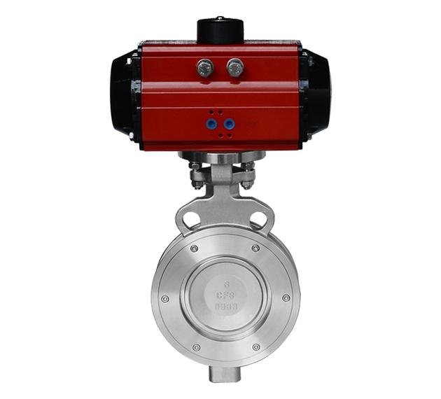
Pneumatische Hochleistungs-Dreifach-Offset-Wafer-Absperrklappe
WDL Valve pneumatic triple offset wafer butterfly valves provide high-temperature, high-pressure and high-cycle shut-off with a multilayer metal seat.
Beschreibung
for reliable shut-off in high-temperature, high-pressure and demanding industrial
pipeline systems. The triple-offset geometry allows the disc to move away from the seat
during operation, minimizing friction and helping protect the sealing surfaces.
The valve uses a multilayer metal sealing arrangement for applications where conventional
soft-seated butterfly valves are not suitable. It is commonly selected for gas, vacuum,
steam and compatible industrial media in power generation, petrochemical, coal chemical,
metallurgy, pulp and paper, textile dyeing and light industry.
Hauptmerkmale
- Triple-offset disc geometry with reduced friction between the disc and seat.
- Multilayer metal seat for high-temperature and high-pressure service.
- Reliable shut-off for high-cycle gas and vacuum applications.
- Pneumatic actuation for fast quarter-turn operation and automation.
- ISO 5211 top mounting platform for actuator installation.
- Precision-cast one-piece body structure.
- Self-lubricating bearing design helps reduce operating torque.
- Graphite packing option for high-temperature stem sealing.
- Stainless steel, duplex, super duplex, titanium, nickel alloy and Monel materials available.
- Manual, worm gear and electric operation available on request.
Triple-Offset Metal Sealing Design
The triple-offset construction is designed so that the disc and seat separate quickly
once the valve begins to open. This reduces sliding contact between the sealing surfaces,
lowers wear and supports long service life. The metal seat structure is suitable for
severe operating conditions involving elevated temperature, pressure or abrasive media.
Technical Specifications
| Artikel | Specification |
|---|---|
| Produkttyp | Pneumatisches Hochleistungs-Dreifach-Offset-Wafer-Absperrklappe |
| Größenauswahl | DN50–DN400 / NPS 2–16 |
| Flange Standard | HG 20592 PN10–PN25, ASME B16.5 Class 150, JIS 10K |
| Face-to-Face Standard | GB/T 12221 und API 609 |
| Sealing Type | Dreifach versetztes mehrschichtiges Metallversiegelungssystem |
| Betrieb | Pneumatic actuator; manual, gear-operated and electric options available |
| Befestigung des Stellantriebs | ISO 5211 |
Main Component Materials
| No. | Komponente | Verfügbare Materialien |
|---|---|---|
| 1 | Ventilkörper | WCB, WCC, CF8, CF8M, CF3, CF3M, 4A, 5A, Titanium Grade 2, Nickel Alloy |
| 2 | Pressure Plate | WCB, WCC, 304, 304L, 316, 316L, 2205, 2507, Titanium Grade 2, Nickel Alloy |
| 3 | Scheibe | CF8, CF8M, CF3, CF3M, 4A, 5A, Titanium Grade 2, Nickel Alloy |
| 4 | Stiel | 17-4PH, 304, 304L, 316, 316L, 2205, 2507, Titanium Grade 2, Nickel Alloy or Monel |
| 5 | Valve Seat | PTFE, RPTFE, TFM, 304, 316, 304L, 316L, 2205, 2507, Titanium Grade 2 or Nickel Alloy |
| 6 | Shaft Sleeve | 201 + PTFE, 316L + PTFE or Monel + PTFE |
| 7 | Packing | PTFE, RPTFE, TFM or graphite |
| 8 | Gland | WCB, WCC, CF8, CF8M, CF3, CF3M, 4A, 5A, Titanium Grade 2 or Nickel Alloy |
| 9 | Bolting | ASTM A193 B7 with ASTM A194 2H nuts |
| 10 | Pin and Retaining Ring | 17-4PH, stainless steel, duplex, super duplex, Titanium Grade 2, Nickel Alloy or Monel |
| 11 | Sealing Gasket | PTFE, RPTFE, TFM or graphite |
Overall and Connection Dimensions
Unit: mm
| DN | NPS | ØA | ØB | C | D | E | F | ØL | H | ØN | ØM1 | 1-(n-ØP) | Custom ØM2 | Custom 2-(n-ØP) | ISO 5211 Mounting Pad |
|---|---|---|---|---|---|---|---|---|---|---|---|---|---|---|---|
| 50 | 2″ | 47 | 100 | 133 | 82 | 16 | 43 | 40 | 11 | 90 | 70 | 4-Ø10 | 50 | 4-Ø8 | F05, F07 |
| 65 | 2.5″ | 64 | 120 | 148 | 96 | 16 | 46 | 58 | 11 | 90 | 70 | 4-Ø10 | 50 | 4-Ø8 | F05, F07 |
| 80 | 3″ | 71 | 132 | 158 | 103 | 16 | 46 | 66 | 11 | 90 | 70 | 4-Ø10 | 50 | 4-Ø8 | F05, F07 |
| 100 | 4″ | 91 | 157 | 180 | 118 | 20 | 52 | 89 | 14 | 92 | 70 | 4-Ø10 | — | — | F07 |
| 125 | 5″ | 111 | 188 | 199 | 133 | 20 | 56 | 109 | 14 | 95 | 70 | 4-Ø10 | — | — | F07 |
| 150 | 6″ | 133 | 216 | 223 | 148 | 23 | 57 | 133 | 17 | 125 | 102 | 4-Ø12 | 70 | 4-Ø10 | F07, F10 |
| 200 | 8″ | 179 | 268 | 260 | 182 | 25 | 62 | 182 | 19 | 125 | 102 | 4-Ø12 | — | — | F10 |
| 250 | 10″ | 225 | 323 | 295 | 242 | 28 | 68 | 218 | 22 | 150 | 125 | 4-Ø14 | 102 | 4-Ø12 | F10, F12 |
| 300 | 12″ | 274 | 375 | 338 | 280 | 30 | 78 | 268 | 27 | 165 | 140 | 4-Ø18 | 125 | 4-Ø14 | F12, F14 |
| 350 | 14″ | 321 | 420 | 370 | 308 | 35 | 92 | 311 | 27 | 195 | 165 | 4-Ø22 | 140 | 4-Ø18 | F14, F16 |
| 400 | 16″ | 371 | 475 | 405 | 340 | 38 | 102 | 360 | 36 | 200 | 165 | 4-Ø22 | — | — | F16 |
Operating Torque Reference
Unit: N·m. Final actuator sizing shall be confirmed by WDL Valve according to the operating conditions.
| DN | NPS | Metal Seat PN6 | Metal Seat PN10 | Metal Seat PN16 | Metal Seat PN25 | Maximum Allowable Torque |
|---|---|---|---|---|---|---|
| 50 | 2″ | 62 | 65 | 65 | 68 | 110 |
| 65 | 2.5″ | 75 | 77 | 82 | 90 | 150 |
| 80 | 3″ | 85 | 88 | 92 | 100 | 150 |
| 100 | 4″ | 120 | 125 | 135 | 145 | 210 |
| 125 | 5″ | 170 | 180 | 200 | 225 | 330 |
| 150 | 6″ | 240 | 255 | 280 | 315 | 400 |
| 200 | 8″ | 340 | 370 | 410 | 465 | 650 |
| 250 | 10″ | 380 | 425 | 590 | 880 | 930 |
| 300 | 12″ | 600 | 660 | 750 | 1100 | 1450 |
| 350 | 14″ | 700 | 850 | 1100 | 1500 | 2200 |
| 400 | 16″ | 1100 | 1400 | 1800 | 2400 | 3500 |
Typische Anwendungsbereiche
- Power generation and steam systems
- Oil, gas and petrochemical processing
- Coal chemical and refinery projects
- Vacuum and high-cycle gas pipelines
- Metallurgie und Industrieofensysteme
- Pulp and paper processing
- Textile dyeing and light industrial plants
Dimensions, materials, torque values and pressure ratings are reference information.
Final valve configuration shall be confirmed by the approved WDL Valve technical drawing
and project datasheet.
Rezensionen
Es gibt noch keine Rezensionen.