
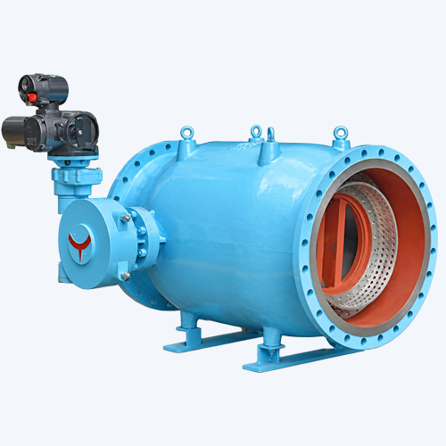
Plunger Flow Control and Pressure Regulating Valve
WDL Valve supplies DN150–DN2000 plunger flow control valves for precise flow and downstream pressure regulation. Multiple cage and vane trim designs are available for high differential pressure, large-flow and water hammer control applications.
Description
WDL Valve plunger flow control valve provides controlled flow and downstream pressure regulation in water transmission, reservoir, pumping and industrial water systems. Its axial-moving cylindrical plunger creates an annular throttling area, giving predictable regulation under high differential pressure and large-flow conditions.
Product Overview
The valve size and internal throttling arrangement are selected according to the system pressure, maximum and minimum flow rates, required pressure reduction and operating conditions. Unlike a conventional control valve, the plunger valve guides the medium through a streamlined, axisymmetric flow passage and controls the outlet through a continuously changing annular opening.
One-piece and segmented body designs are available. The combined plunger and multifunction seat can be configured for shut-off, fine regulation, high pressure drop or high flow. Cage-type options include LH perforated-cylinder, LL double-layer perforated-cylinder, SZ multi-slot and XT special designs. Vane-type options include the E venting seat and S vane-ring seat. Project-specific trim can be engineered when standard arrangements do not meet the hydraulic requirements.
How the Plunger Valve Works
A crank-and-slider mechanism moves the cylindrical plunger along the pipeline centreline. As the plunger approaches or moves away from the seat, the annular flow area changes and regulates flow or downstream pressure. The streamlined internal passage guides the water evenly, reduces hydraulic resistance and limits head loss. The controlled closing profile is fast during the initial travel and slower near the seat, helping reduce pressure surges and water hammer.
Main Components and Control Options
The main valve consists of the body, outlet body, valve seat, plunger, cage or vane ring, stem, crank, connecting rod, bushings, guide rails, plunger support and sealing rings. Available automation packages include an electric actuator, PLC control system, pressure transmitters and flowmeters.
| Product Type | Plunger flow control and pressure regulating valve |
|---|---|
| Nominal Size | DN150–DN2000 |
| Pressure Ratings | PN6 and PN10 shown; other ratings available by project review |
| Body Configuration | One-piece or segmented body |
| Trim Options | LH, LL, SZ, XT cage type; E and S vane type |
| Operation | Electric actuator with optional PLC, pressure transmitter and flowmeter |
| Typical Service | Water transmission, pressure reduction, reservoir control, pump discharge and large-flow regulation |
Key Features
- Axial plunger movement provides a continuously variable annular throttling area.
- Near-linear regulating characteristics support stable flow and pressure control.
- Streamlined axisymmetric passage reduces turbulence, resistance and head loss.
- Constant output torque and controlled closing motion improve operating stability.
- Closing speed decreases near the seat to help limit water hammer.
- Multiple cage and vane trims are available for fine control, high pressure drop and large flow.
- Electric actuation and closed-loop PLC control can be supplied.
- Internal components can be customised using project hydraulic data.
Main Connection Dimensions
Dimensions are in millimetres. The symbols L, D, K, d, b, f and z–d0 correspond to the manufacturer’s dimensional drawing.
| PN | DN | L | D | K | d | b | f | z–d0 |
|---|---|---|---|---|---|---|---|---|
| PN6 | 150 | 350 | 265 | 225 | 199 | 20 | 2 | 8–Ø18 |
| 200 | 400 | 320 | 280 | 254 | 22 | 2 | 8–Ø18 | |
| 250 | 500 | 375 | 335 | 309 | 24 | 2 | 12–Ø18 | |
| 300 | 600 | 440 | 395 | 363 | 24 | 2 | 12–Ø22 | |
| 350 | 700 | 490 | 445 | 413 | 24 | 2 | 12–Ø22 | |
| 400 | 800 | 540 | 495 | 463 | 24 | 2 | 16–Ø22 | |
| 450 | 900 | 595 | 550 | 518 | 24 | 2 | 16–Ø22 | |
| 500 | 1000 | 645 | 600 | 568 | 26 | 2 | 20–Ø22 | |
| 600 | 1200 | 755 | 705 | 667 | 30 | 2 | 20–Ø26 | |
| 700 | 1400 | 860 | 810 | 772 | 26 | 5 | 24–Ø26 | |
| 800 | 1600 | 975 | 920 | 878 | 26 | 5 | 24–Ø30 | |
| 900 | 1800 | 1075 | 1020 | 978 | 26 | 5 | 24–Ø30 | |
| 1000 | 2000 | 1175 | 1120 | 1078 | 26 | 5 | 28–Ø30 | |
| 1200 | 2400 | 1405 | 1340 | 1295 | 28 | 5 | 32–Ø30 | |
| 1400 | 2800 | 1630 | 1560 | 1510 | 32 | 5 | 36–Ø36 | |
| 1600 | 3200 | 1830 | 1760 | 1710 | 34 | 5 | 40–Ø36 | |
| 1800 | 3600 | 2045 | 1970 | 1918 | 36 | 5 | 44–Ø39 | |
| 2000 | 4000 | 2265 | 2180 | 2125 | 38 | 5 | 48–Ø42 | |
| PN10 | 150 | 350 | 285 | 240 | 211 | 24 | 2 | 8–Ø22 |
| 200 | 400 | 340 | 295 | 266 | 24 | 2 | 8–Ø22 | |
| 250 | 500 | 395 | 350 | 319 | 26 | 2 | 12–Ø22 | |
| 300 | 600 | 445 | 400 | 370 | 26 | 2 | 12–Ø22 | |
| 350 | 700 | 505 | 460 | 429 | 26 | 2 | 16–Ø22 | |
| 400 | 800 | 565 | 515 | 480 | 26 | 2 | 16–Ø26 | |
| 450 | 900 | 615 | 565 | 530 | 28 | 2 | 20–Ø26 | |
| 500 | 1000 | 670 | 620 | 582 | 28 | 2 | 20–Ø26 | |
| 600 | 1200 | 780 | 725 | 682 | 34 | 2 | 20–Ø30 | |
| 700 | 1400 | 895 | 840 | 794 | 34 | 5 | 24–Ø30 | |
| 800 | 1600 | 1015 | 950 | 901 | 36 | 5 | 24–Ø33 | |
| 900 | 1800 | 1115 | 1050 | 1001 | 38 | 5 | 28–Ø33 | |
| 1000 | 2000 | 1230 | 1160 | 1112 | 38 | 5 | 28–Ø36 | |
| 1200 | 2400 | 1455 | 1380 | 1328 | 44 | 5 | 32–Ø39 | |
| 1400 | 2800 | 1675 | 1590 | 1530 | 48 | 5 | 36–Ø42 | |
| 1600 | 3200 | 1915 | 1820 | 1750 | 52 | 5 | 40–Ø48 | |
| 1800 | 3600 | 2115 | 2020 | 1950 | 56 | 5 | 44–Ø48 | |
| 2000 | 4000 | 2325 | 2230 | 2150 | 60 | 5 | 48–Ø48 |
Information Required for Selection
Please provide the pipe size, design and operating pressure, upstream and downstream pressure, minimum/normal/maximum flow, medium, temperature, required control accuracy, installation orientation, actuator power supply and control signal. WDL Valve will select the body size, cavitation-control trim and actuator according to the hydraulic conditions.
The dimensions above were transcribed from the supplied source table. All dimensions, materials, pressure limits, actuator selection and cavitation performance must be confirmed by the final approved WDL Valve drawing and technical datasheet before ordering.
Reviews
There are no reviews yet.